| Menu Category |
SubMenu |
Comment |
Configuration |
| BASIC |
D/R,EXP |
Dual rates and Exponential |
Switch = B
Activate D/R and EXP = Position UP
Not Active:
Channel1 Aileron: D/R=100%, Exp = 0%
Channel2 Elevator: D/R=100%, Exp = 0%
Channel4 Rudder: D/R=100%, Exp = 0%
Active:
Channel1 Aileron: D/R=100%, Exp = -15%
Channel2 Elevator: D/R=100%, Exp = -15%
Channel4 Rudder: D/R=100%, Exp = -5% |
| BASIC |
END POINT |
I noticed that the swash plate
linkage rods where driven "out of range" or binding with max pitch
combined with max cyclic roll and cyclic pitch.
Tried to adjust individual servo end points to
compensate. Discovered this does not work for an H3 CCPM swash
config. The individual servos become none linear (when moving in a
CCPM setting)as the radio treats the end point range as a full throw
for each servo. CH1,2 and 6 must have the same endpoints in an H3
CCPM Swash configuration. |
Channel1: Aileron =
100 / 100
Channel2: Elevator = 100 / 100
Channel3: Throttle = 140 / 140
Channel4: Rudder = 100/100
Channel5: GyroGain = 100/100
Channel6: Collective Pitch = 100 / 100
Channel7: Auxiliary = 100/100Note
for reference (Futaba has defined the following)::
CH1 - 4 is defined as 40 degrees servo throw = 100% endpoint
CH5 - 7 (and 8) is defined as 55 degrees servo throw = 100% endpoint |
| BASIC |
SUB-TRIM |
|
Channel1: Aileron =
-31
Channel2: Elevator = -32
Channel3: Throttle = 0
Channel4: Rudder = 0
Channel5: GyroGain = 0
Channel6: Collective Pitch = +18
Channel7: Auxiliary = 0 |
| BASIC |
REVERSE |
|
Channel1: Aileron =
NORMAL
Channel2: Elevator = NORMAL
Channel3: Throttle = REVERSE
Channel4: Rudder = NORMAL (this depends on which way you twist the
tail belt! )
Channel5: GyroGain = NORMAL
Channel6: Collective Pitch = REVERSE
Channel7: Auxiliary = NORMAL |
| BASIC |
TRIM |
|
Aileron = 4
Elevator = 4
Throttle = 4
Rudder = 4 |
| BASIC |
THROTTLE-CUT |
Very useful as emergency switch.
As it is long and easy to quickly flick with your left hand little
finger. Thus minimise the crash damage.
Saved me many times!
|
Rate = 0%
Throttle = 100% (Throttle stick has to be below this value before
throttle re-engage after a throttle cut operation. Decided not
needed on the TREX250 so left the value at 100%.)
Switch = F
Position = DOWN |
| BASIC |
SWASH AFR |
Automatic Function Rate
Set the rate (Travel) of the set of servos involved in a function
Collective is calibrated to give about 13 deg in
IDL2
Aileron and Elevator is calibrated to ensure
that servos don't go passed limits in IDL2 mode with max pitch and
max on Aileron/Elevator. (Cyclic roll/cyclic pitch) |
Aileron = -55%
(start with 50% for a nice steady hover and move up)
Elevator = +55% (start with 50% for a nice steady hover and move up)
Collective Pitch = +41%Notes:
This method is trading a more lively responds on cyclic roll and
cyclic pitch in order to ensure safe operation of the servos for
extreme movements of the sticks in IDL2 mode (IDL2 as defined on on
this webpage). The only way to safely increase the values for Cyclic
Roll (Aileron) and Cyclic pitch (Elevator)is to install stick
movement limiters on the radio. (Mechanical ring fitted onto the
cyclic stick preventing movement into the corners (which is the
source of the problem) |
| BASIC |
F/S |
Fail Safe
|
Channel 3: Throttle
F/S = 1%, i.e. cut throttle if signal is lost. Thus, let the
helicopter fall to ground.NOR = Normal.
Servos retain their last position just before the Error situation
happened
FailSafe = Move servos to a pre-programmed position |
| BASIC |
AUX-CH |
|
Channel 5 = NULL,
Note Channel 5 is GyroGain. When Gyro Sense = Active, Channel 5 is
Automatically associated with Ch5 and is overriding whatever is
configured in this menu
Channel 6 = ---
Channel 7 = VR(C). I use this channel to program a LiPo voltage guard unit
mounted on the heli. |
| BASIC |
PARAMETER |
Automatic Travel Limit is
relevant for Nitro machines only, but doesn't hurt in the Trex250
setup so left ON. |
Type = Helicopter
Swash = HR3 (120deg CCPM)
Module = 2.4GHz / 7 Channel (using the Futaba R617FS receiver)
ATL = ON |
| BASIC |
REVO. MIX |
Rudder control...
if Gyro is not
used |
INHIBITED |
| BASIC |
TIMER |
|
Timer1 set to 7
minutes countdown. Start when throttle stick crosses 11%. (up). Reset when
Switch A = Down. |
| ADVANCED |
THR-CURVE |
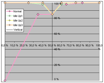
Throttle-Curves;
Normal mode:
I decided to alter the throttle curve
such that headspeed is retained with good marging below midstick
position. Reason is that an overreaction when pull-back on the stick
generates a double negative if headspeed is lost, and the heli hits
the ground as a consequence.
Set midstick throttle at 85% according to manual
to keep rotospeed below maxspeed. |
|
Throttle Curves |
|
Mode: |
Normal |
|
Idle Up1 |
Idle Up2 |
Idle Up3 |
|
Stick Position |
Output |
Stick Position |
Output |
Output |
Output |
|
|
|
|
|
|
|
|
100,0 % |
100,0 % |
100,0 % |
100,0 % |
100,0 % |
100,0 % |
|
82,0 % |
100,0 % |
75,0 % |
100,0 % |
100,0 % |
100,0 % |
|
65,0 % |
98,0 % |
60,0 % |
98,0 % |
100,0 % |
100,0 % |
|
60,0 % |
98,0 % |
50,0 % |
85,0 % |
85,0 % |
85,0 % |
|
50,0 % |
85,0 % |
40,0 % |
98,0 % |
100,0 % |
100,0 % |
|
35,0 % |
85,0 % |
25,0 % |
100,0 % |
100,0 % |
100,0 % |
|
0,0 % |
0,0 % |
0,0 % |
100,0 % |
100,0 % |
100,0 % |
|
 |
| ADVANCED |
PITCH-CURVE |
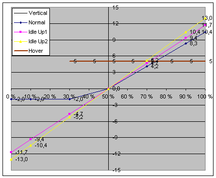
Pitch Curves
Pitch curves were derived as follows:
1/ Set collective pitch curve to 100%
2/ Reduced SWASH AFR Pitch setting until Pitch Gauge show 13degrees
3/ This is defined as max performance in IDL2
4/ Adapt performance for Normal and IDL1 as shown in tables
Comment:
My experience is that IDL1 definition is nice and stable to control,
yet you need this "power" if the conditions are e.g. windy.
If you take it down to max pitch at e.g. 9 degrees. make sure you
fly in a "no wind" condition. |
|
Pitch Curves |
|
Mode: |
Normal |
Normal |
|
Idle Up1 |
Idle Up1 |
Idle Up2 |
Idle Up2 |
|
Stick |
Output |
Pitch |
Stick |
Output |
Pitch |
Output |
Pitch |
|
|
|
|
|
|
|
|
|
|
100,0 % |
80,0 % |
10,4 |
100,0 % |
90,0 % |
11,7 |
100,0 % |
13,0 |
|
90,0 % |
64,0 % |
8,3 |
90,0 % |
72,0 % |
9,4 |
80,0 % |
10,4 |
|
70,0 % |
32,0 % |
4,2 |
70,0 % |
36,0 % |
4,7 |
40,0 % |
5,2 |
|
50,0 % |
0,0 % |
0,0 |
50,0 % |
0,0 % |
0,0 |
0,0 % |
0,0 |
|
30,0 % |
-15,0 % |
-2,0 |
30,0 % |
-36,0 % |
-4,7 |
-40,0 % |
-5,2 |
|
10,0 % |
-15,0 % |
-2,0 |
10,0 % |
-72,0 % |
-9,4 |
-80,0 % |
-10,4 |
|
0,0 % |
-15,0 % |
-2,0 |
0,0 % |
-90,0 % |
-11,7 |
-100,0 % |
-13,0 |
|
|
 |
| ADVANCED |
GYRO SENSE |
Gyro Gain settings |
MIX =
Active
MODE = GY
Switch = Conditional (this implies that it follows the conditions
listed underneath)Rate-NORMAL = AVC 24%
Rate-IDL1 = AVC 22%
Rate-IDL2 = AVC 22%
Rate-IDL3 = AVC 22%
Rate-HOLD = NOR 15% (this way it possible to test the tail movement
before take-off, Flick HOLD switch and test the tailblades responds
to Rudder input.) |
| ADVANCED |
REVO.MIX |
Relevant if not Gyro
present |
Inhibited |
| ADVANCED |
THR-HOLD |
Throttle Hold |
POSI =
-50% (slow turn on the rotor for vibration check) |
| ADVANCED |
HOV-THR |
|
Inhibited |
| ADVANCED |
HOV-PIT |
|
Inhibited |
| ADVANCED |
HI/LO-PIT |
Maximum travel
Pitch. Maybe used to change hi/lo side of pitch curve in-flight.
(Not used) |
HI-PITch
= 100%
ADJ = Manual
LO-PITch = 100%
ADJ = Manual |
| ADVANCED |
OFFSET |
Trim data |
Inhibited |
| ADVANCED |
DELAY |
Smoothing delay when
jumping between the various modes (Normal -> IDL1 etc)
Futaba defines 50% = 0,5seconds |
AILE =
20%
ELEV = 20%
RUDD = 0%
THRO = 20%
PITC = 20%(Note; there is no way to
enter the servo speed into the radio. Thus, there is no(!)
correlation to the actual gyro speed which Bob Finley states in his
excellent FUTABA 10C video) |
| ADVANCED |
GOVERNOR |
|
Inhibited |
| ADVANCED |
THROTTLE-MIX |
For nitro machines |
Inhibited |
| ADVANCED |
THR_NEEDLE |
For nitro machines |
Inhibited |
| ADVANCED |
PROG:MIX1-6 |
|
Inhibited |
| ADVANCED |
CONDITION SELECT |
Sets the switch
associated with CONDITION found in the Throttle and Pitch curve menu |
IDLE-UP1
= Switch E in CENTRE position
IDLE-UP2 = Switch E in DOWN position
IDLE-UP3 = Inhibited
THR-HOLD = Switch G in DOWN position
NORMAL mode is then defined as Switch E in UP position as this
position is not defined by any of the Condition settings above. |